CP/M Operating System Manual
Section 3
CP/M Assembler
Table of Contents
3.1 Introduction
3.2 Program Format
3.3 Forming the Operand
3.3.1 Labels
3.3.2 Numeric Constants
3.3.3 Reserved Words
3.3.4 String Constants
3.3.5 Arithmetic and Logical Operators
3.3.6 Precedence of Operators
3.4 Assembler Directives
3.4.1 The ORG Directive
3.4.2 The END Directive
3.4.3 The EQU Directive
3.4.4 The SET Directive
3.4.5 The IF and ENDIF Directive
3.4.6 The DB Directive
3.4.7 The DW Directive
3.4.8 The DS Directive
3.5 Operation Codes
3.5.1 Jumps, Calls, and Returns
3.5.2 Immediate Operand Instructions
3.5.3 Increment and Decrement Instructions
3.5.4 Data Movement Instructions
3.5.5 Arithmetic Logic Unit Operations
3.5.6 Control Instructions
3.6 Error Messages
3.7 A Sample Session
Tables
3-1 Reserved Characters
3-2 Arithmetic and Logical Operations
3-3 Assembler Directives
3-4 Jumps, Calls, and Returns
3-5 Immediate Operand Instructions
3-6 Increment and Decrement Instructions
3-7 Data Movement Instructions
3-8 Arithmetic Logic Unit Operations
3-9 Error Codes
3-10 Error Messages
The CP/M assembler reads assembly-language source files from the disk and produces 8080 machine language in Intel hex format. To start the CP/M assembler, type a command in one of the following forms:
     ASM filename
     ASM filename.parms
In both cases, the assembler assumes there is a file on the disk with the name:
filename.ASM
which contains an 8080 assembly-language source file. The first and second forms shown above differ only in that the second form allows parameters to be passed to the assembler to control source file access and hex and print file destinations.
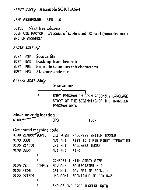
In either case, the CP/M assembler loads and prints the message:
CP/M ASSEMBLER VER n.n
where n.n is the current version number. In the case of the first command, the assembler reads the source file with assumed filetype ASM and creates two output files
     filename.HEX
     filename.PRN
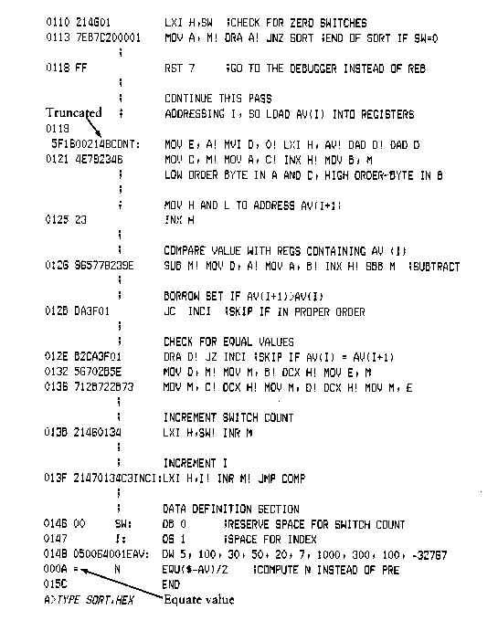
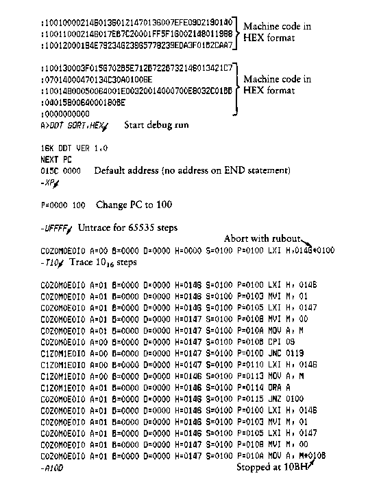
The HEX file contains the machine code corresponding to the original program in Intel hex format, and the PRN file contains an annotated listing showing generated machine code, error flags, and source lines. If errors occur during translation, they are listed in the PRN file and at the console.
The form ASM filename parms is used to redirect input and output files from their defaults. In this case, the parms portion of the command is a three-letter group that 'fies the origin of the source file, the destination of the hex file, and the destination of the print file. The form is
filename.p1p2p3
where p1, p2, and p3 are single letters. P1 can be
A,B,...,P
which designates the disk name that contains the source file. P2 can be
A,B,...,P
which designates the disk name that will receive the hex file; or, P2 can be
Z
which skips the generation of the hex file.
P3 can be
A,B,...,P
which designates the disk name that will receive the print file. P3 can also be specified as
X
which places the listing at the console; or
Z
which skips generation of the print file. Thus, the command
ASM X.AAA
indicates that the source, X.HEX and print, X.PRN files are also to be created on disk A. This form of the command is implied if the assembler is run from disk A. Given that you are currently addressing disk A, the above command is the same as
ASM X
The command
ASM X.ABX
indicates that the source file is to be taken from disk A, the hex file is to be placed on disk B, and the listing file is to be sent to the console. The command
ASM X.BZZ
takes the source file from disk B and skips the generation of the hex and print files. This command is useful for fast execution of the assembler to check program syntax.
The source program format is compatible with the Intel 8080 assembler. Macros are not implemented in ASM; see the optional MAC macro assembler. There are certain extensions in the CP/M assembler that make it somewhat easier to use. These extensions are described below.
An assembly-language program acceptable as input to the assembler consists of a sequence of statements of the form
line# label operation operand ;comment
where any or all of the fields may be present in a particular instance. Each assemblylanguage statement is terminated with a carriage return and line-feed (the line-feed is inserted automatically by the ED program), or with the character !, which is treated as an end-of-line by the assembler. Thus, multiple assembly-language statements can be written on the same physical line if separated by exclamation point symbols.
The line# is an optional decimal integer value representing the source program line number, and ASM ignores this field if present.
The label field takes either of the following forms:
     identifier
     identifier:
The label field is optional, except where noted in particular statement types. The identifier is a sequence of alphanumeric characters where the first character is alphabetic. Identifiers can be freely used by the programmer to label elements such as program steps and assembler directives, but cannot exceed 16 characters in length. All characters are significant in an identifier, except for the embedded dollar symbol $, which can be used to improve readability of the name. Further, all lower-case alphabetics are treated as upper-case. The following are all valid instances of labels:
| x | xy | long$name |
| x: | yxl: | longer$naned$data: |
| X1Y2 | X1x2 | x234$5678$9012$3456: |
The operation field contains either an assembler directive or pseudo operation, or an 8080 machine operation code. The pseudo operations and machine operation codes are described in Section 3.3.
Generally, the operand field of the statement contains an expression formed out of constants and labels, along with arithmetic and logical operations on these elements. Again, the complete details of properly formed expressions are given in Section 3.3.
The comment field contains arbitrary characters following the semicolon symbol untill the next real or logical end-of-line. These characters are read, listed, and otherwise ignored by the assembler. The CP/M assembler also treats statements that begin with an * in column one as comment statements that are listed and ignored in the assembly process.
The assembly-language program is formulated as a sequence of statements of the above form, terminated by an optional END statement. All statements following the END are ignored by the assembler.
To describe the operation codes and pseudo operations completely, it is necessary first to present the form of the operand field, since it is used in nearly all statements. Expressions in the operand field consist of simple operands, labels, constants, and reserved words, combined in properly formed subexpressions by arithmetic and logical operators. The expression computation is carried out by the assembler as the assembly proceeds. Each expression must produce a 16-bit value during the assembly. Further, the number of significant digits in the result must not exceed the intended use. If an expression is to be used in a byte move immediate instruction, the most significant 8 bits of the expression must be zero. The restriction on the expression significance is given with the individual instructions.
A label is an identifier that occurs on a particular statement. In general, the label is given a value determined by the type of statement that it precedes. If the label occurs on a statement that generates machine code or reserves memory space (for example, a MOV instruction or a DS pseudo operation), the label is given the value of the program address that it labels. If the label precedes an EQU or SET, the label is given the value that results from evaluating the operand field. Except for the SET statement, an identifier can label only one statement.
When a label appears in the operand field, its value is substituted by the assembler. This value can then be combined with other operands and operators to form the operand field for a particular instruction.
A numeric constant is a 16-bit value in one of several bases. The base, called the radix of the constant, is denoted by a trailing radix indicator. The following are radix indicators:
| B | is a binary constant (base 2). |
| O | is a octal constant (base 8). |
| Q | is a octal constant (base 8). |
| D | is a decimal constant (base 10). |
| H | is a hexadecimal constant (base 16). |
Q is an alternate radix indicator for octal numbers because the letter O is easily confused with the digit 0. Any numeric constant that does not terminate with a radix indicator is a decimal constant.
A constant is composed as a sequence of digits, followed by an optional radix indicator, where the digits are in the appropriate range for the radix. Binary constants must be composed of 0 and 1 digits, octal constants can contain digits in the range 0-7, while decimal constants contain decimal digits. Hexadecimal constants contain decimal digits as well as hexadecimal digits A(10D), B(11D), C(12D), D(13D), E(14D), and F(15D). Note that the leading digit of a hexadecimal constant must be a decimal digit to avoid confusing a hexadecimal constant with an identifier. A leading 0 will always suffice. A constant composed in this manner must evaluate to a binary number that can be contained within a 16-bit counter, otherwise it is truncated on the right by the assembler.
Similar to identifiers, embedded $ signs are allowed within constants to improve their readability. Finally, the radix indicator is translated to upper-case if a lower-case letter is encountered. The following are all valid instances of numeric constants:
| 1234 | 1234D | 1100B | 1111$0000$1111$0000B |
| 1234H | 0FFEH | 3377O | 33$77$22Q |
| 3377o | 0fe3h | 1234d | 0ffffh |
There are several reserved character sequences that have
predefined meanings in the operand field of a statement. The
names of 8080 registers are given below. When they are
encountered, they produce the values shown to the right.
Character Value
A 7
B 0
C 1
D 2
E 3
H 4
L 5
M 6
SP 6
PSW 6
Again, lower-case names have the same values as their upper-case equivalents. Machine instructions can also be used in the operand field; they evaluate to their internal codes. In the case of instructions that require operands, where the specific operand becomes a part of the binary bit pattern of the instruction, for example, MOV A,B, the value of the instruction, in this case MOV, is the bit pattern of the instruction with zeros in the optional fields, for example, MOV produces 40H.
When the symbol $ occurs in the operand field, not embedded within identifiers and numeric constants, its value becomes the address of the next instruction to generate, not including the instruction contained within the current logical line.
String constants represent sequences of ASCII characters and are represented by enclosing the characters within apostrophe symbols. All strings must be fully contained within the current physical line (thus allowing exclamation point symbols within strings) and must not exceed 64 characters in length. The apostrophe character itself can be included within a string by representing it as a double apostrophe (the two keystrokes"), which becomes a single apostrophe when read by the assembler. In most cases, the string length is restricted to either one or two characters (the DB pseudo operation is an exception), in which case the string becomes an 8- or 16-bit value, respectively. Two-character strings become a 16-bit constant, with the second character as the low-order byte, and the first character as the high-order byte.
The value of a character is its corresponding ASCII code. There is no case translation within strings; both upper- and lower-case characters can be represented. You should note that only graphic printing ASCII characters are allowed within strings.
| Valid strings: | How assembler reads strings: |
|---|---|
| 'A' 'AB' 'ab' 'c' | A AB ab c |
| '' 'a''' '''' '''' | a ''' |
| 'Walla Walla Wash.' | Walla Walla Wash |
| 'She said "Hello" to me.' | She said "Hello" to me. |
| 'I said "Hello" to her.' | I said "Hello" to her. |
3.3.5 Arithmetic and Logical Operators
The operands described in
Section 3.3 can be combined in normal
algebraic notation using any combination of properly formed
operands, operators, and parenthesized expressions. The operators
recognized in the operand field are described in
Table 3-2.
Operators Meaning
a + b unsigned arithmetic sum of a and b
a - b unsigned arithmetic difference between a and b
+ b unary plus (produces b)
- b unary minus (identical to 0 - b)
a * b unsigned magnitude multiplication of a and b
a / b unsigned magnitude division of a by b
a MOD b remainder after a / b.
NOT b logical inverse of b (all 0s become 1s, 1s
become 0s), where b is considered a 16-bit
value
a AND b bit-by-bit logical and of a and b
a OR b bit-by-bit logical or of a and b
a XOR b bit-by-bit logical exclusive or of a and b
a SHL b the value that results from shifting a to the
lef by an amount b, with zero fill
a SHR b the value that results from shifting a to the
right by an amount b, with zero fill
In each case, a and b represent simple operands (labels, numeric constants, reserved words, and one- or two-character strings) or fully enclosed parenthesized subexpressions, like those shown in the following examples:
     10+20 10h+37Q L1/3 (L2+4) SHR3
     ('a' and 5fh)+'O'('B'+B)OR(PSW+M)
     (1+(2+c))shr(A-(B+1))
Note that all computations are performed at assembly time as 16-bit unsigned operations. Thus, -1 is computed as 0 - 1, which results in the value 0ffffh (that is, all 1s). The resulting expression must fit the operation code in which it is used. For example, if the expression is used in an ADI (add immediate) instruction, the high-order 8 bits of the expression must be zero. As a result, the operation ADI -1 produces an error message (-1 becomes 0ffffh, which cannot be represented as an 8-bit value), while ADI (-1) AND 0FFH is accepted by the assembler because the AND operation zeros the high-order bits of the expression.
As a convenience to the programmer, ASM assumes that operators have a relative precedence of application that allows the programmer to write expressions without nested levels of parentheses. The resulting expression has assumed parentheses that are defined by the relative precedence. The order of application of operators in unparenthesized expressions is listed below. Operators listed first have highest precedence (they are applied first in an unparenthesized expression), while operators listed last have lowest precedence. Operators listed on the same line have equal precedence, and are applied from left to right as they are encountered in an expression.
     * / MOD SHL SHR
     - +
     NOT
     AND
     OR XOR
Thus, the expressions shown to the left below are interpreted by the assembler as the fully parenthesized expressions shown to the right.
| a*b+c | (a*b) + c |
| a+b*c | a + (b*c) |
| a MOD b*c SHL d | ((a MOD b) * c) SHL d |
| a OR b AND NOT c+d SHL e | a OR (b AND (NOT (c + (d SHL e)))) |
Balanced, parenthesized subexpressions can always be used to override the assumed parentheses; thus, the last expression above could be rewritten to force application of operators in a different order, as shown:
( a OR b ) AND ( NOT c ) + d SHL e
This results in these assumed parentheses:
(a OR b ) AND ( (NOT c ) + ( d SHL e ) )
An unparenthesized expression is well-formed only if the expression that results from inserting the assumed parentheses is well-formed.
Assembler directives are used to set labels to specific values
during the assembly, perform conditional assembly, define storage
areas, and specify starting addresses in the program. Each
assembler directive is denoted by a pseudo operation that appears
in the operation field of the line. The acceptable pseudo
operations are shown in
Table 3-3.
Directive Meaning
ORG set the program or data origin
END end program, optional start address
EQU numeric equate
SET numeric set
IF begin conditional assembly
ENDIF end of conditional assembly
DB define data bytes
DW define data words
DS define data storage area
The ORG statement takes the form:
where label is an optional program identifier and expression is a
16-bit expression, consisting of operands that are defined before
the ORG statement. The assembler begins machine code generation
at the location specified in the expression. There can be any
number of ORG statements within a particular program, and there
are no checks to ensure that the programmer is not defining
overlapping memory areas. Note that most programs written for the
CP/M system begin with an ORG statement of the form:
which causes machine code generation to begin at the base of the
CP/M transient program area. If a label is specified in the ORG
statement, the label is given the value of the expression. This
label can then be used in the operand field of other statements
to represent this expression.
The END statement is optional in an assembly-language program,
but if it is present it must be the last statement. All
subsequent statements are ignored in the assembly. The END
statement takes the following two forms:
where the label is again optional. If the first form is used, the
assembly process stops, and the default starting address of the
program is taken as 0000. Otherwise, the expression is evaluated,
and becomes the program starting address. This starting address
is included in the last record of the Intel-formatted machine
code hex file that results from the assembly. Thus, most CP/M
assembly-language programs end with the statement:
resulting in the default starting address of 100H (beginning of
the transient program area).
The EQU (equate) statement is used to set up synonyms for
particular numeric values. The EQU statement takes the form:
where the label must be present and must not label any other
statement. The assembler evaluates the expression and assigns
this value to the identifier given in the label field. The
identifier is usually a name that describes the value in a more
human-oriented manner. Further, this name is used throughout the
program to place parameters on certain functions. Suppose data
received from a teletype appears on a particular input port, and
data is sent to the teletype through the next output port in
sequence. For example, you can use this series of equate
statements to define these ports for a particular hardware
environment:
At a later point in the program, the statements that access the
teletype can appear as follows:
making the program more readable than if the absolute I/O ports
are used. Further, if the hardware environment is redefined to
start the teletype communications ports at 7FH instead of 10H,
the first statement need only be changed to
and the program can be reassembled without changing any other
statements.
The SET statement is similar to the EQU, taking the form:
except that the label can occur on other SET statements within
the program. The expression is evaluated and becomes the current
value associated with the label. Thus, the EQU statement defines
a label with a single value, while the SET statement defines a
value that is valid from the current SET statement to the point
where the label occurs on the next SET statement. The use of the
SET is similar to the EQU statement, but is used most often in
controlling conditional assembly.
The IF and ENDIF statements define a range of assembly-language
statements that are to be included or excluded during the
assembly process. These statements take on the form:
When encountering the IF statement, the assembler evaluates the
expression following the IF. All operands in the expression must
be defined ahead of the IF statement. If the expression evaluates
to a nonzero value, then statement#l through statement#n are
assembled. If the expression evaluates to zero, the statements
are listed but not assembled. Conditional assembly is often used
write a single generic program that includes a number of
possible run-time environments, with only a few specific portions
of the program selected for any particular assembly. The
following program segments, for example, might be part of a
program that communicates with either a teletype or a CRT console
(but not both) by selecting a particular value for TTY before the
assembly begins.
In this case, the program assembles for an environment where a
teletype is connected, based at port 10H. The statement defining
TTY can be changed to
and, in this case, the program assembles for a CRT based at port
20H.
The DB directive allows the programmer to define initialized
storage areas in singleprecision byte format. The DB statement
takes the form:
where e#1 through e#n are either expressions that evaluate to 8-bit
values (the highorder bit must be zero) or are ASCII strings
of length no greater than 64 characters. There is no practical
restriction on the number of expressions included on a single
source line. The expressions are evaluated and placed
sequentially into the machine code file following the last
program address generated by the assembler. String characters are
similarly placed into memory starting with the first character
and ending with the last character. Strings of length greater
than two characters cannot be used as operands in more
complicated expressions.
3.4.1 The ORG Directive
label ORG expression
ORG 100H
     label END
     label END expression
END 100H
label EQU expression
     TTYBASE   EQU 10H        ;BASE PORT NUMBER FOR TTY
     TTYIN     EQU TTYBASE    ;TTY DATA IN
     TTYOUT    EQU TTYBASE+1  ;TTY DATA OUT
     IN  TTYIN      ;READ TTY DATA TO REG-A
        ....

     OUT TTYOUT     ;WRITE DATA TO TTY FROM REG-A
TTYBASE EQU 7FH ;BASE PORT NUMBER FOR TTY
label SET expression
3.4.5 The IF and ENDIF Directives
     IF expression
     statement# 1
     statement#2
         ...
     statement#n
     ENDIF
     TRUE    EQU  0FFFFH      ;DEFINE VALUE OF TRUE
     FALSE   EQU  NOT TRUE    ;DEFINE VALUE OF FALSE
     ;
     TTY     EQU  TRUE        ;TRUE IF TTY, FALSE IF CRT
     ;
     TTYBASE EQU  10H         ;BASE OF TTY I/O PORTS
     CRTBASE EQU  20H         ;BASE OF CRT I/O PORTS
             IF   TTY         ;ASSEMBLE RELATIVE TO
                              ;TTYBASE
     CONIN   EQU  TTYBASE     ;CONSOLE INPUT
     CONOUT  EQU  TTYBASE+1   ;CONSOLE OUTPUT
             ENDIF
     ;
             IF   NOT TTY     ;ASSEMBLE RELATIVE TO
                              ;CRTBASE
     CONIN   EQU  CRTBASE     ;CONSOLE INPUT
     CONOUT  EQU  CRTBASE+1   ;CONSOLE OUTPUT
             ENDIF
             ...
             IN   CONIN       ;READ CONSOLE DATA
             OUT  CONTOUT     ;WRITE CONSOLE DATA
TTY EQU FALSE
label DB e#1, e#2, ... , e#n
| Note: | ASCII characters are always placed in memory Note: Note: with the parity bit reset (0). Also, there is no translation from lower- to upper-case within strings. |
|---|
The optional label can be used to reference the data area throughout the remainder of the program. The following are examples of valid DB statements:
     data:     DB  0,1,2,3,4,5
               DB  data and 0ffh,5,377Q,1+2+3+4
     sign-on:  DB  'please type your name',CR,LF,0
               DB  'AB' SHR 8,'C','DE',AND 7FH
The DW statement is similar to the DB statement except double- precision two-byte words of storage are initialized. The DW statement takes the form:
label DW e#1, e#2, ..., e#n
where e#1 through e#n are expressions that evaluate to 16-bit results. Note that ASCII strings of one or two characters are allowed, but strings longer than two characters are disallowed. In all cases, the data storage is consistent with the 8080 processor; the least significant byte of the expression is stored first in memory, followed by the most significant byte. The following are examples of DW statements:
     doub: DW 0ffefh,doub+4,signon-$,255+255
           DW 'a',5,'ab','CD',6 shl 8 or llb.
The DS statement is used to reserve an area of uninitialized memory, and takes the form:
label DS expression
where the label is optional. The assembler begins subsequent code generation after the area reserved by the DS. Thus, the DS statement given above has exactly the same effect as the following statement:
     label: EQU $            ;LABEL VALUE IS CURRENT CODE LOCATION
            ORG $+expression ;MOVE PAST RESERVED AREA
Assembly-language operation codes form the principal part of assembly-language programs and form the operation field of the instruction. In general, ASM accepts all the standard mnemonics for the Intel 8080 microcomputer, which are given in detail in the Intel 8080 Assembly Language Programming Manual. Labels are optional on each input line. The individual operators are listed briefly in the following sections for completeness, although the Intel manuals should be referenced for exact operator details. In Tables 3-4 through 3-8, bit values have the following meaning:
- e3 represents a 3-bit value in the range 0-7 that can be one of the predefined registers A, B, C, D, E, H, L, M, SP, or PSW.
- e8 represents an 8-bit value in the range 0-255.
- e16 represents a 16-bit value in the range 0-65535.
These expressions can be formed from an arbitrary combination of operands and operators. In some cases, the operands are restricted to particular values within the allowable range, such as the PUSH instruction. These cases are noted as they are encountered.
In the sections that follow, each operation code is listed in its most general form, along with a specific example, a short explanation, and special restrictions.
3.5.1 Jumps, Calls, and Returns
The Jump, Call, and Return instructions allow several different forms that test the condition flags set in the 8080 microcomputer CPU. The forms are shown in Table 3-4.
3.5.2 Immediate Operand Instructions
Several instructions are available that load single- or double-precision registers or single-precision memory cells with constant values, along with instructions that perform immediate arithmetic or logical operations on the accumulator (register A). Table 3-5 describes the immediate operand instructions.
3.5.3 Increment and Decrement
Instructions
The 8080 provides instructions for incrementing or decrementing single- and double precision registers. The instructions are described in Table 3-6.
3.5.4 Data Movement Instructions
Instructions that move data from memory to the CPU and from CPU to memory are given in the following table.
3.5.5 Arithmetic Logic Unit
Operations
Instructions that act upon the single-precision accumulator to perform arithmetic and logic operations are given in the following table.
The four remaining instructions, categorized as control instructions, are the following:
- HLT halts the 8080 processor.
- DI disables the interrupt system.
- EI enables the interrupt system.
- NOP means no operation.
When errors occur within the assembly-language program, they are listed as singlecharacter flags in the leftmost position of the source listing. The line in error is also echoed at the console so that the source listing need not be examined to determine if errors are present. The error codes are listed in the following table.
Table 3-10 lists the error messages that are
due to terminal
error conditions.
Table 3-10. Error Messages
